To Create a Socially-Distanced Waiting Area
The model must have accessible spaces defined. If accessible spaces are not defined, the command start methods are disabled, and the command cannot be started.
-
Start the
Socially-Distanced Waiting
Area command
 .
.
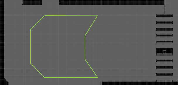
- Draw the waiting area boundary, using either the rectangle or polygon drawing mode:
-
The Socially-distanced Waiting Area Options dialog appears.
Configure social distancing in the waiting area by doing the following:
- Set the Social distancing value. The default is 2.00 meters (or imperial equivalent).
- Select a Waiting Object type - choose one of these:
- Select a Layout style. Choose one of these:
- (Optional) Check the option to include or exclude Waiting Zones or Delay Points which intersect the boundary.
- Review the Object count. It displays how many objects are created when the command is complete.
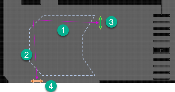
- Identify a Base point which is the reference point for the object array.
-
Mark the
row direction. What happens next depends on
the selected
Layout style option.
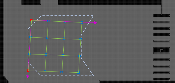
- For the Freeform layout, you can make bespoke row and column angle selections.
- For the Grid layout, the objects are arranged as a square grid (oriented to row direction). The Column direction may be set at +/- 90° from the row angle.
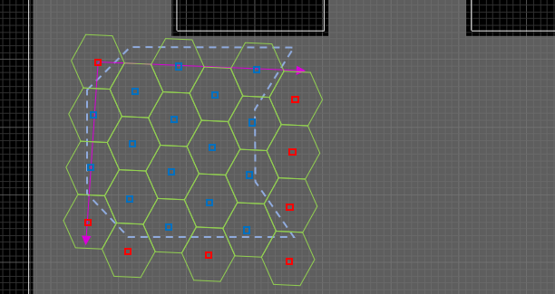
- For the Hexagon layout, the objects are arranged as a hexagonal grid (oriented to row direction). The Column direction has certain characteristics:
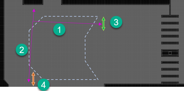
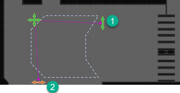
- Base point, row direction and (where applicable) column direction are adjustable during the command (subject to the limits of the chosen Layout method).
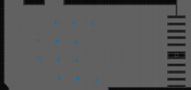
- During the command, example Waiting Zone/Delay Point positions are shown based on the selected options.
- Press <Enter> to complete the command.
- Upon completion, a Waiting Zone or Delay Point property dialog is shown. Set the object details. All objects created by the command will share these details.
- Click OK to close the property dialog, and add the objects to the model.